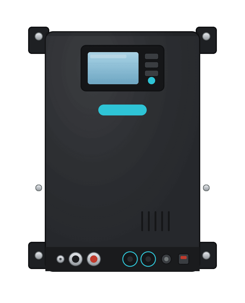
Inverter grounding is not one wire and it is not a universal diagram. A safe RV installation has to coordinate the inverter manual, the AC distribution equipment, shore power, any generator and the transfer method between sources.
Do not add a neutral-ground jumper by guesswork
An incorrect bond or an unswitched neutral can place current on protective conductors, defeat the intended fault path, cause nuisance GFCI operation or leave exposed metal energized. Use listed equipment and have the completed 120V system inspected by a qualified RV or marine electrician.
The three connections people often confuse
| Connection | Normal purpose | What it is not |
|---|---|---|
| DC negative | Returns battery current to the DC source | Automatically the same thing as AC equipment ground |
| Inverter chassis/bonding terminal | Connects exposed metal to the specified protective bonding system | A substitute for the large DC negative conductor |
| AC equipment-grounding conductor | Provides a low-impedance fault path for downstream AC equipment | A normal current-carrying neutral |
The vehicle chassis may participate in the DC bonding and AC protective system, but only as specified by the equipment manufacturer and applicable installation standard. It should not carry normal inverter DC load current in place of correctly sized positive and negative battery cables.
The source determines the neutral-ground behavior
An RV can have several possible 120V sources:
- campground shore power;
- a standalone inverter;
- an inverter-charger operating in inverter mode;
- a generator.
Neutral and equipment ground should not be joined at arbitrary downstream panels or receptacles. The required source bond and neutral switching depend on which source is active and on the design of the listed transfer equipment.
Standalone inverter
Do not assume every standalone inverter bonds neutral internally. Some outputs are floating, some products establish a bond, and some manufacturers specify how GFCI protection and downstream distribution must be arranged. Read the installation manual for the exact model, not merely the brand family.
Inverter-charger with shore power
Many listed inverter-chargers coordinate an internal transfer relay and grounding relay. In inverter mode the unit may establish the required source relationship; when qualified shore power is present it may remove that internal relationship because the supply provides it. That behavior is product-specific and must not be recreated with an uncontrolled jumper.
External transfer switch
The transfer switch must be suitable for the sources and neutral arrangement being switched. A device that switches only the ungrounded conductor is not interchangeable with one designed to switch the neutral as well. Follow the inverter, transfer-switch and panel instructions as a complete system.
A safe design review sequence
- List every possible AC source and confirm whether two sources can ever be connected simultaneously.
- Obtain the installation manual and wiring diagram for the exact inverter or inverter-charger model.
- Identify whether its AC output is floating, internally bonded or relay-switched in each operating mode.
- Confirm how the shore cord, inlet, overcurrent protection, transfer equipment and distribution panel are listed and connected.
- Keep neutral isolated from equipment ground in downstream distribution unless the approved system documentation explicitly says otherwise.
- Size the chassis/bonding conductor and DC cables from the manufacturer instructions, current, length and protection requirements.
- Verify polarity, protective-conductor continuity, source transfer and GFCI operation with suitable test equipment before use.
GFCI protection is not a substitute for correct bonding
GFCI protection compares current leaving and returning on the circuit conductors. It reduces shock risk, but it does not make an improvised neutral-ground arrangement safe. A GFCI can also trip because of leakage or an unintended parallel neutral path, so persistent trips should be diagnosed rather than bypassed.
What to record for an inspection
Keep the inverter model and manual revision, transfer-switch model, panel diagram, conductor sizes, protective device ratings and test results with the van. This makes later troubleshooting safer and prevents a future owner from adding a second bond because the original design is unclear.
Related
Frequently Asked Questions
Keep the build moving
Make the next build decision easier.
Get practical diagrams, calculator updates and honest product comparisons in your inbox.
Roam Wired
Roam Wired turns campervan research into practical plans. We publish transparent guidance, a free electrical design tool and marketplace resources for UK and US van builders.
About our approach