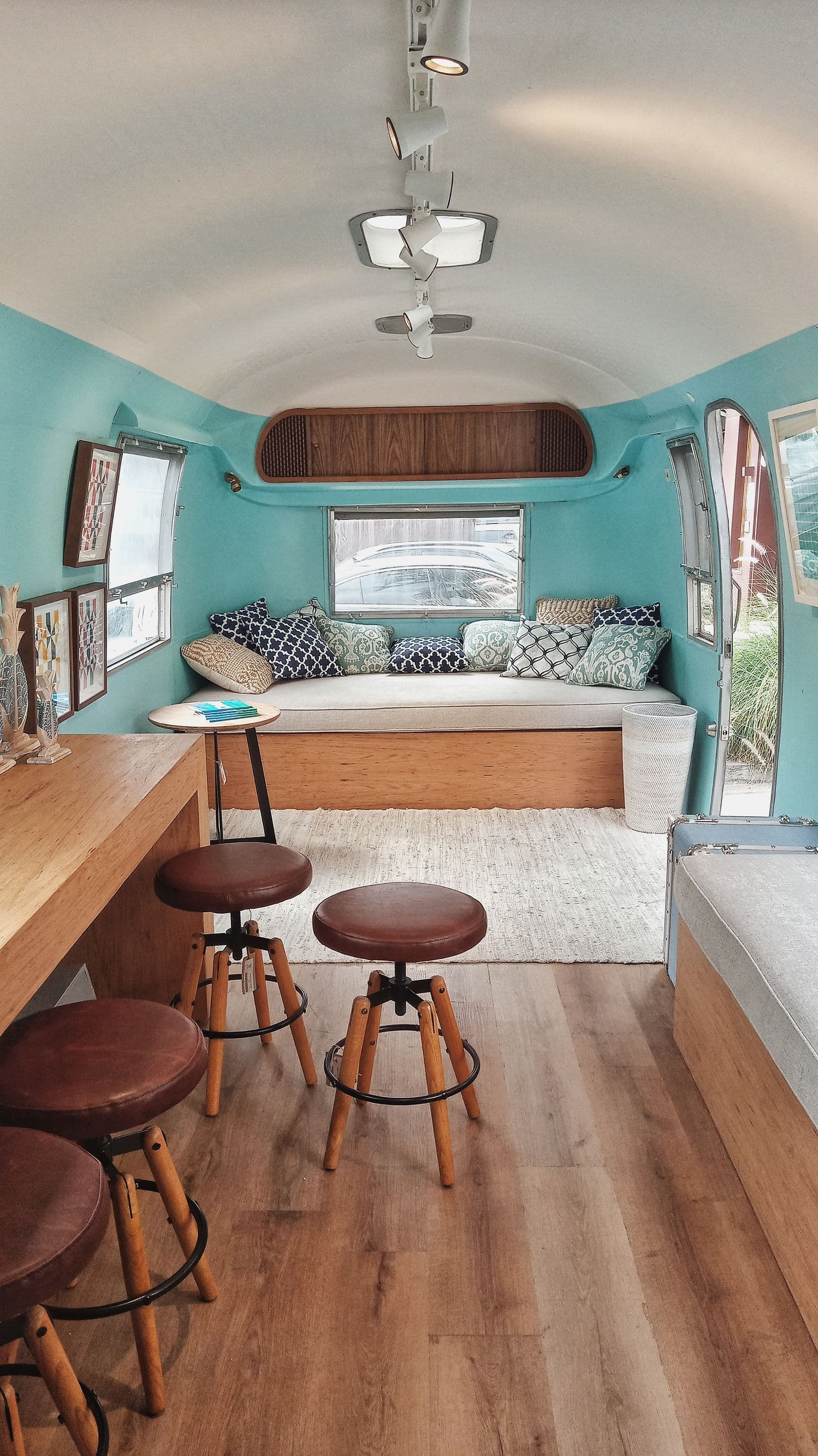
The Chevrolet Express and GMC Savana can support a capable camper electrical system, but a safe design starts with the exact van rather than a universal diagram.
Size the system from your actual loads
Estimate battery, solar and inverter requirements before choosing component ratings or cable routes.
Record the van details first
Before buying an isolator or DC-DC charger, record:
- model year, engine and gross vehicle weight rating;
- VIN-specific alternator and battery options;
- any factory auxiliary-battery or upfitter provisions;
- starting-battery location and approved connection points;
- roof type, doors, windows and planned penetrations;
- intended house-battery and electrical-cabinet location.
The Express has existed across many model years and commercial configurations. Claims such as "all Express vans have a fixed-voltage alternator" are too broad for design work.
Alternator charging
A current-limited DC-DC charger gives the designer control over charge voltage and input current, which is useful for lithium house batteries and long cable runs. It does not remove the need to confirm what the vehicle manufacturer permits.
Use this sequence:
- Check VIN-specific GM service or body-builder information.
- Confirm approved positive connection and return/bonding points.
- Measure charging behavior during start-up, idle, cruising and high electrical load.
- Check the house battery's permitted charge current and temperature restrictions.
- Select a DC-DC current that the vehicle and house battery can support.
- Size both conductors and end protection from the charger's maximum input current, not only its advertised output.
Do not copy a blanket AWG recommendation. A long front-to-rear run at 30A may require a different conductor than a short run at the same current because voltage drop and installation temperature differ.
Battery and equipment placement
A useful electrical bay keeps high-current paths short while remaining accessible for inspection. It should also protect terminals from stored cargo and keep heat-producing equipment within its required clearances.
Check each location for:
- structural restraint in a crash;
- clearance from seat mounts, fuel and brake systems;
- battery operating and charging temperature;
- water ingress and condensation;
- service access to fuses, disconnects and terminals;
- ventilation required by the chosen equipment;
- inverter distance from the battery bank.
Avoid using exposed sheet-metal screws as assumed high-current bonding points. Use manufacturer-approved points or an engineered connection prepared and protected against corrosion.
Solar layout on an Express roof
Usable solar area depends on wheelbase, roof conversion, vents, fans, antennas, shading and safe edge clearances. Measure the real roof and map every obstruction before selecting panels.
Panel wattage should follow the energy budget, not a claim about what "normally fits." A smaller array with low shading can outperform a larger array broken into poorly placed sections.
A practical system-design order
- Build a daily energy budget for refrigeration, lighting, water, charging and AC appliances.
- Choose battery capacity for the required autonomy and allowable depth of discharge.
- Size solar from seasonal use and measured roof space.
- Size alternator charging from the vehicle, battery and drive pattern.
- Choose the inverter only after listing simultaneous AC loads and surge requirements.
- Draw the system with disconnects, fuses, bus bars and cable lengths.
- Verify every terminal and conductor rating before installation.
Related
Frequently Asked Questions
Keep the build moving
Make the next build decision easier.
Get practical diagrams, calculator updates and honest product comparisons in your inbox.
Roam Wired
Roam Wired turns campervan research into practical plans. We publish transparent guidance, a free electrical design tool and marketplace resources for UK and US van builders.
About our approach