Wiring is where a van conversion can go badly wrong. Not aesthetically wrong — electrically wrong. Undersized cables that overheat. Unfused positive runs that turn into fuses themselves when they short. Improperly earthed 230V circuits that are a silent electrocution risk.
This guide is the complete reference for wiring a campervan electrical system safely and correctly. It covers cable sizing from first principles, fuse selection, the bus bar architecture, earthing requirements, 230V safety standards, and how to verify everything before you switch it on.
This is part of our complete campervan electrical system guide. For the components being wired, see the battery guide, charging guide, and inverter guide.
Get a custom wiring diagram
Our calculator generates a complete wiring diagram with every wire gauge and fuse rating calculated for your specific system.
Why Wiring Safety Is Non-Negotiable
A LiFePO4 battery has an internal resistance of approximately 1–3 milliohms. At 12V, a direct short circuit across its terminals can draw several thousand amps — briefly, before something fails. That "something" should be a fuse. If there's no fuse, it's the wire insulation that gives way first — and burning wire insulation in a van is how van fires start.
The three causes of campervan electrical fires:
- Undersized wire carrying more current than it can handle, overheating and melting insulation
- An unfused positive cable contacting the van body (chassis) and creating a dead short
- A corroded or loose connection with high resistance generating heat at the junction
All three are entirely preventable through correct cable sizing, universal fusing, and quality installation.
The 12V DC Wiring Architecture
The Bus Bar System
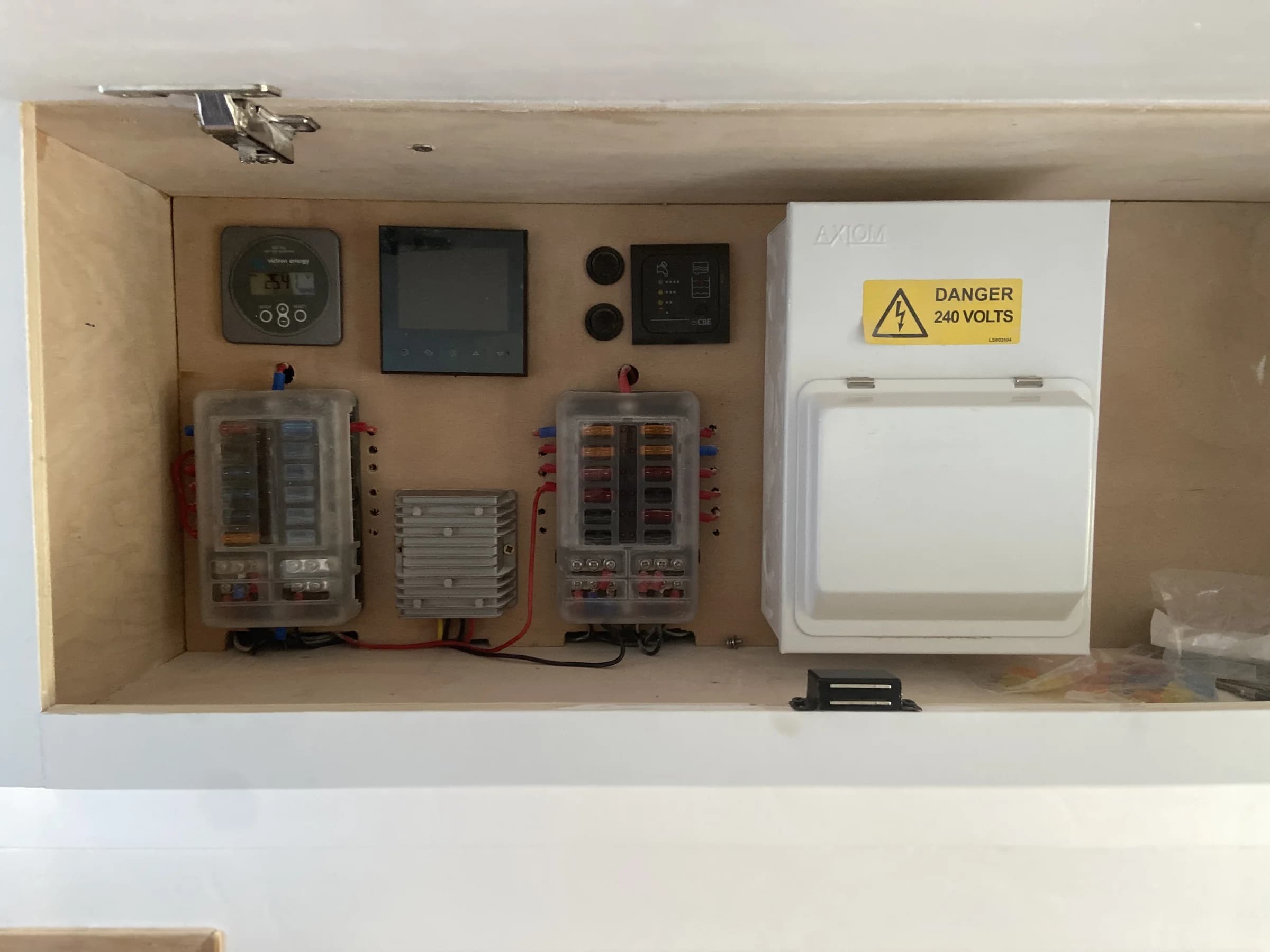
The standard architecture for a campervan electrical system routes everything through a positive bus bar and a negative bus bar. The battery connects to the bus bars via the main fused cable; every charge source and every load connects to the bus bars, not directly to the battery.
Why bus bars instead of direct connection:
- A single ANL fuse on the main battery-to-bus-bar cable protects the entire system
- Adding circuits is clean: run a new cable to the bus bar, add a fuse
- The SmartShunt on the negative main cable measures every amp in and out
- The wiring is logical and traceable
Positive bus bar: Connects to the battery positive terminal via a fused cable. Every positive output (to fuse box, inverter, MPPT, DC-DC, mains charger) connects here.
Negative bus bar: Connects to the battery negative terminal via the SmartShunt. Every negative return connects here. The chassis earth also connects here.
Typical connections at each bus bar:
| Positive Bus Bar | Negative Bus Bar |
|---|---|
| From battery (+) via ANL fuse | From battery (−) via SmartShunt |
| To blade fuse box (via 70A fuse) | From blade fuse box negative returns |
| To inverter ANL fuse (via cable) | From inverter negative |
| From MPPT controller output (+) | From MPPT controller output (−) |
| From DC-DC charger output (+) | From DC-DC charger output (−) |
| From mains charger output (+) | From mains charger output (−) |
| To chassis earth bond |
Negative Bus Bar and Chassis Earthing
The negative bus bar (or battery negative) must be connected to the vehicle's chassis at a clean, unpainted, corrosion-free metal point. This is called the chassis earth bond.
Why a chassis earth is needed:
For the 12V system: some 12V devices earth themselves through the vehicle body (particularly those bolted to the van — some diesel heaters, water pump controllers, and aftermarket accessories). Without a chassis earth, these devices have no return path for their negative current.
For the 230V system: the chassis earth is part of the shock protection circuit. Any fault current on 230V wiring must have a path to earth to trip the RCD. If the chassis isn't bonded to earth, a 230V fault to the chassis doesn't trip the RCD — it just sits there at 230V, potentially lethal.
Making the chassis earth connection:
Find a clean metal point — ideally a factory-drilled, unpainted hole in the chassis cross-member or floor strengthening. Grind off any coating or rust from a 30mm circle. Use a ring terminal of adequate size (minimum 10mm² for the chassis earth wire), secure with a bolt and nut (not a self-tapping screw). Apply anti-corrosion spray or petroleum jelly to the joint after installation.
Test the connection with a multimeter in continuity mode between the negative bus bar and bare metal at various chassis points — should read close to 0 ohms.
Cable Sizing: From First Principles
Why Cable Sizing Matters
Every cable has a resistance determined by its cross-sectional area and length. When current flows, this resistance converts electrical energy into heat (P = I² × R). A thin wire carrying too much current gets hot. Hot enough, the insulation melts. Melted insulation shorts to adjacent wires or to the van body, causing a fire.
Cable current ratings exist to define the maximum current a cable can carry without its insulation temperature exceeding the rated limit. Standard automotive cable (PVC insulation, rated to 70°C) has different current ratings than high-temperature cable (rated to 105°C).
There are two constraints to consider:
- Ampacity: The maximum current the cable can carry without overheating
- Voltage drop: The acceptable voltage loss along the cable length
UK Cable Sizing: mm² Cross-Section
UK wiring is specified in mm² (square millimetres of cross-sectional area). This is not the same as AWG (American Wire Gauge, used in the US) — don't substitute AWG charts for UK mm² specifications.
Cable ampacity table (PVC insulated, 70°C, installed in bundles or enclosed spaces):
| Cable Size | Max Current (single cable, free air) | Max Current (bundled/enclosed) |
|---|---|---|
| 1.0mm² | 16A | 11A |
| 1.5mm² | 20A | 14A |
| 2.5mm² | 27A | 19A |
| 4.0mm² | 37A | 25A |
| 6.0mm² | 47A | 33A |
| 10mm² | 65A | 45A |
| 16mm² | 87A | 60A |
| 25mm² | 114A | 80A |
| 35mm² | 138A | 98A |
| 50mm² | 168A | 119A |
| 70mm² | 213A | 150A |
Use the "bundled/enclosed" column for cables run inside conduit, cable ducts, or trunking. Use the "free air" column only for cables with genuine airflow around them.
Important note: These are the cable's own thermal limits. The fuse must be sized to protect the cable — the fuse rating must not exceed the "bundled/enclosed" current rating for the cable size used.
Voltage Drop Calculation
Voltage drop is the reduction in voltage along a cable due to resistance. At 12V, a 3% maximum voltage drop is the standard target — that's 0.36V.
The formula:
Voltage drop (V) = Current (A) × Cable resistance per metre (Ω/m) × Length (m, both ways)
Cable resistance per metre (both conductors combined):
| Cable Size | Resistance per metre (both ways, at 20°C) |
|---|---|
| 1.5mm² | 25.9 mΩ/m |
| 2.5mm² | 15.2 mΩ/m |
| 4.0mm² | 9.54 mΩ/m |
| 6.0mm² | 6.44 mΩ/m |
| 10mm² | 3.66 mΩ/m |
| 16mm² | 2.35 mΩ/m |
| 25mm² | 1.48 mΩ/m |
| 35mm² | 1.06 mΩ/m |
| 50mm² | 0.73 mΩ/m |
Worked example: fridge circuit
Fridge (Waeco CFX35) draws maximum 8A. Cable run from fuse box to fridge: 3.5m (positive + negative = 7m total).
Using 1.5mm² cable: 8A × 0.0259Ω/m × 7m = 1.45V drop = 12% — far too high. Using 2.5mm² cable: 8A × 0.0152Ω/m × 7m = 0.85V drop = 7.1% — still too high. Using 4mm² cable: 8A × 0.00954Ω/m × 7m = 0.53V drop = 4.5% — marginal. Using 6mm² cable: 8A × 0.00644Ω/m × 7m = 0.36V drop = 3.0% — exactly at the limit.
For this fridge at 3.5m one-way run: 6mm² is required if you want to stay within the 3% voltage drop target.
In practice, most builders would use 4mm² for this circuit and accept the slightly higher voltage drop — fridge compressors tolerate some voltage variation. But for sensitive electronics or circuits where voltage accuracy matters, size to the 3% target.
Online calculators: See campervan cable size calculator for a tool that does this calculation automatically.
Circuit-by-Circuit Sizing Guide
For a typical mid-range UK van build:
| Circuit | Max Current | One-Way Length | Required Size | Fuse Rating |
|---|---|---|---|---|
| LED lighting (all zones) | 5A | 4m | 1.5mm² | 7.5A |
| USB charging sockets | 5A | 3m | 1.5mm² | 7.5A |
| 12V socket (general) | 10A | 3m | 2.5mm² | 15A |
| Compressor fridge | 8A | 4m | 4mm² | 10A |
| Water pump | 8A | 4m | 4mm² | 10A |
| Diesel heater | 8A | 3m | 2.5mm² | 10A |
| DC-DC charger output | 30A | 2m | 10mm² | 40A |
| MPPT controller output | 30A | 2m | 10mm² | 40A |
| Mains charger output | 30A | 2m | 10mm² | 40A |
| Fuse box main feed | 60A | 1m | 16mm² | 70A ANL |
| Inverter (1000W) | 100A | 0.8m | 35mm² | 125A ANL |
| Main battery to bus bar | 150A | 1m | 35mm² | 175A ANL |
Cable Quality: What You Must Use
Tinned copper, fine-stranded automotive or marine cable is the correct specification for campervan wiring. This provides:
- Corrosion resistance (tin coating on each strand prevents copper oxidation in the damp environment)
- Flexibility (fine stranding allows repeated bending without fatigue failure)
- High-temperature PVC or cross-linked polyethylene insulation
What NOT to use:
- Standard house wiring (twin and earth): Solid core — cracks from vibration. PVC rated for only 70°C in enclosed conditions. Not suitable.
- Extension lead cable: Flexible, but thin strands of un-tinned copper oxidise in humid conditions. Not rated for sustained vehicle use.
- Cheap no-name automotive cable: Copper content often below stated spec. Some "copper" wire is copper-clad aluminium — much higher resistance and difficult to solder/crimp reliably.
Reputable sources for quality cable in the UK: Bimble Solar, Auto Electrical Supplies, Vehicle Wiring Products, Lapp Group distributors.
Fusing: Protecting the Wiring
What Fuses Protect
A common misconception: fuses protect the appliance. They don't. Fuses protect the wire.
A fuse rated below the wire's current capacity will blow if the current exceeds the fuse rating, disconnecting the circuit before the wire overheats. If the fuse is rated above the wire's capacity, the fuse won't blow even as the wire overheats — the wire becomes the fuse, which is how fires start.
Rule: The fuse must be rated below the cable's maximum current capacity, not above the load's expected draw.
Fuse Placement: The 300mm Rule
The fuse must be placed within 300mm of the point where the positive cable taps off from the power source (bus bar or battery). This is because the unfused section of cable between the source and the fuse is unprotected — if anything contacts that section, the full fault current flows through it. Keeping this section to 300mm minimises the risk.
This applies to every positive cable in the system:
- Main cable from battery to bus bar: ANL fuse within 300mm of battery positive terminal
- Inverter cable from bus bar: ANL fuse within 300mm of bus bar tap-off point
- Individual circuit cables from fuse box: fuses are inside the fuse box at the start of each cable
- DC-DC charger input cable at starter battery: fuse within 300mm of starter battery positive
Types of Fuses
ANL (Bolt-Through) Fuses:
ANL fuses are used for high-current, high-stakes circuits: the main battery cable, inverter feed, and large charge source connections. They're physically large fuses that bolt into a two-terminal fuse holder.
Available ratings: 60A, 80A, 100A, 125A, 150A, 175A, 200A, 250A, 300A, 400A.
ANL fuse holders must be rated for the full expected current and are available in 300A and 500A versions. Use quality holders — cheap plastic holders can develop high-resistance contacts under vibration.
MIDI/MEGA Fuses:
MIDI fuses are a compact alternative to ANL for currents up to 100A. MEGA fuses go up to 500A. Both use a similar bolt-through construction. MIDI fuses are appropriate for DC-DC charger input cables and MPPT output cables in the 30–60A range.
Blade Fuses (ATO/ATC):
Standard automotive blade fuses. Used in fuse boxes for individual 12V circuits. Available in 1A, 2A, 3A, 5A, 7.5A, 10A, 15A, 20A, 25A, 30A.
Most campervan circuit wiring is sized for 10–20A blade fuses per circuit. Use a fuse box (12-way, 18-way) with individual slots and covers.
MCBs (Miniature Circuit Breakers):
MCBs are the 230V equivalent of blade fuses — they trip (rather than blow) when overcurrent flows and can be manually reset. Used in consumer units for 230V circuits.
For 12V systems, MCBs are sometimes used instead of blade fuses for convenience (resettable) but are more expensive and bulkier. They're more common in marine installations than campervans.
Fuse Sizing Guide
For each circuit, the fuse must satisfy two conditions:
- Less than the cable's maximum current rating
- Greater than the circuit's maximum expected load
For individual 12V circuits:
| Cable Size | Max Fuse Rating | Suitable For |
|---|---|---|
| 1.0mm² | 10A | Low-current circuits, LED lights |
| 1.5mm² | 13A | Lights, USB sockets |
| 2.5mm² | 20A | USB, 12V sockets, small appliances |
| 4.0mm² | 30A | Fridge, pump, diesel heater |
| 6.0mm² | 40A | High-current 12V circuits |
| 10mm² | 60A | MPPT and DC-DC charger outputs |
| 16mm² | 80A | Main fuse box feed |
For ANL fuses (main and inverter circuits):
Match the ANL fuse to the cable's ampacity (free air, since these cables usually have space around them):
| Cable Size | ANL Fuse Rating |
|---|---|
| 25mm² | 100A |
| 35mm² | 125A or 150A |
| 50mm² | 200A |
| 70mm² | 250A or 300A |
Connections: Crimping
Every connection in a campervan electrical system should be crimped with a ratchet crimper using tinned copper ring terminals or ferrules. This is non-negotiable for reliability.
Why Crimped, Not Soldered
A soldered joint seems strong, but:
- Vibration failure: Solder creates a rigid point in a flexible conductor. Repeated vibration causes metal fatigue at the solder boundary, developing cracks and high-resistance failure points — often after months or years, which makes them very difficult to diagnose.
- Cold solder joints: A poorly soldered joint has higher resistance than a properly soldered joint. Under high current, this resistance causes heating and potential failure.
- Thermal cycling: Campervans experience significant temperature swings. Different thermal expansion coefficients between copper, solder, and insulation cause stress at the joint over time.
A properly crimped connection deforms both the terminal barrel and the conductors into a gas-tight, homogeneous contact with minimal resistance. It's mechanically stable under vibration and thermally robust.
What "properly crimped" means:
Use a ratchet crimper (Knipex, CK, or similar quality brand — not a cheap generic). Ratchet crimpers apply consistent, calibrated force and won't release until the crimp is complete. The result is a repeatable, correct-depth deformation.
Match terminal size to cable size: every quality terminal range (Cembre, SWA, Burndy) specifies the compatible cable size. Don't cram a 16mm² cable into a terminal rated for 10mm².
After crimping, apply adhesive-lined heat shrink over the crimp joint. This adds mechanical support, protects against corrosion, and prevents the terminal from pulling off the cable insulation.
Connectors for Different Applications
Ring terminals: For permanent connections at bus bars, battery terminals, and shunt connections. The ring sits over a stud and is secured with a nut. Cannot come undone accidentally.
Anderson SB50 connectors: High-current (up to 120A) quick-connect/disconnect connectors used for DC-DC charger connections, portable solar inputs, and any connection that needs to be easily disconnectable. Not inherently waterproof — add rubber boots for exterior use.
Deutsch DTM connectors: Multi-pin waterproof connectors (IP67). Excellent for exterior connections, solar panel junction boxes, and roof-mounted equipment. Require a specific crimping tool (the Deutsch HDT-48-00 hand tool).
Wagos and push-in connectors: Not suitable for campervan use. These are designed for household wiring with low vibration; in a van they can develop intermittent contact over time.
Butt splices: Use only crimp-type butt splices (not solder sleeve or push-in types) and apply adhesive-lined heat shrink over the joint. For permanent, in-wall connections that will never need to be accessed again.
Colour Codes
Consistent colour coding makes your wiring system understandable to anyone who works on it — including you in a year's time when you've forgotten what that unlabelled wire does.
UK/European 12V DC colour conventions:
| Wire | Standard Colour |
|---|---|
| Positive (always live) | Red |
| Negative / Earth return | Black |
| Positive (switched) | Any colour except red/black, often yellow or blue |
| Ignition sense wire | White or grey |
| Chassis earth | Green/yellow or bare copper |
UK 230V AC colour conventions (post-2006):
| Wire | Colour |
|---|---|
| Live | Brown |
| Neutral | Blue |
| Earth | Green/Yellow |
The pre-2006 colours (red live, black neutral) should not be used in new installations. If you encounter them in existing caravan or motorhome wiring, treat both red and black as potentially live until verified.
Labelling: Even with consistent colour coding, label both ends of every cable with a description (e.g., "FRIDGE +", "MPPT OUT +"). Clip-on cable labels, printed heat shrink, or even a marker on tape are all acceptable.
230V AC Wiring: Safety Requirements
The 230V wiring in a campervan must be treated with the same seriousness as house wiring. The voltages are identical; the risks are identical.
Cable Specification for 230V
All 230V circuits must use:
- Minimum 2.5mm² cross-section per conductor (supports 20A circuits)
- Three-core flexible cable: brown (L), blue (N), green/yellow (E)
- Flexible stranded (Class 5) conductor — not solid core
- PVC insulation rated to 60°C or above
Standard "3-core flex" from any electrical supplier meets this specification. Don't use 1.5mm² for 230V circuits in a campervan, even for low-draw loads — the minimum standard is 2.5mm².
RCD (Residual Current Device) Requirements
Every 230V circuit — whether powered from shore power, inverter, or both — must be protected by a 30mA RCD.
What an RCD does: Monitors the current flowing in the live conductor and compares it to the current returning in the neutral conductor. In a fault-free circuit, these are equal. If there's a leakage to earth (e.g., someone is being electrocuted, or a live wire is contacting the van body), some current takes the leakage path instead of returning through neutral. The RCD detects this imbalance — as small as 30mA — and disconnects the circuit within 30ms.
Type A vs Type F:
Type A RCDs respond to sinusoidal AC and pulsating DC fault currents. Type F additionally responds to high-frequency fault currents that can occur with modern variable-frequency drives and some inverters. Either is suitable for a basic campervan installation; Type F is preferable if you have a sophisticated inverter or multi-phase equipment.
Double-pole RCD:
Use a double-pole RCD for campervan installations — it disconnects both the live and neutral simultaneously. Single-pole RCDs (which disconnect only the live) can leave the neutral live in some fault conditions. In a van with imperfect neutral-earth bonding, double-pole is the safe choice.
Testing the RCD:
The RCD has a TEST button. Press it every 3–6 months. The RCD should trip instantly. If it doesn't trip, the RCD is faulty and must be replaced — a non-functioning RCD provides no protection.
After installation, additionally test with a socket tester (a plug-in device with three indicator lights). This verifies correct wiring polarity and that the RCD is functional.
Consumer Unit
For more than two 230V circuits, install a small consumer unit. This provides:
- A main isolator switch for all 230V circuits
- Individual MCBs (Miniature Circuit Breakers) per circuit — protects cable, provides easy isolation for maintenance
- A central earth terminal
A 4-way or 6-way consumer unit is appropriate for most van builds. Wire it as you would a domestic consumer unit: RCD output feeds the consumer unit's live busbars; individual MCBs connect to each circuit.
MCB sizing for 230V circuits:
| Circuit | MCB Rating |
|---|---|
| Ring socket circuit (2.5mm² cable) | 16A or 20A |
| Dedicated mains charger | 16A |
| Induction hob | 16A |
| General lighting (230V, if any) | 6A |
The Neutral-Earth Bond
In a shore power connected van, the grid provides the neutral-earth reference. The RCD at the campsite hook-up box or at the van inlet provides protection.
In a van running on inverter power alone, the inverter's output neutral must be bonded to earth (vehicle chassis). Without this bond:
- If a live wire contacts the chassis, no fault current flows (there's no return path) — the RCD won't trip
- The chassis may be at a hazardous voltage relative to true earth
How to implement the neutral-earth bond:
Many inverters (including all Victron Phoenix and MultiPlus models) have the neutral-earth bond built in — the inverter's output neutral is internally connected to its earth terminal, which connects to the chassis.
Verify this in your inverter's manual before adding an external bond. If the inverter already has an internal bond, don't add an external one — double bonding can cause issues with earth current.
For vans with both inverter and shore power:
The neutral-earth bond must be present when on inverter power and absent when on shore power (the grid provides the bond). A Victron MultiPlus handles this automatically with its internal transfer relay. For separate inverter + shore power systems, a manual changeover switch ensures only one source is connected to the consumer unit at a time — eliminating the possibility of both bonds being active simultaneously.
Testing and Commissioning
Before Powering Up: The Pre-Power Checklist
This is worth doing methodically — finding a problem before the system is live is much safer than diagnosing it after.
12V system checks:
- Main ANL fuse is NOT inserted (leave out until all other checks complete)
- Main positive cable: battery (+) → ANL fuse holder → positive bus bar — check connections are tight
- Main negative cable: battery (−) → SmartShunt → negative bus bar — check connections are tight
- Chassis earth: negative bus bar → clean bare metal on chassis — check connection is sound
- Every positive circuit cable is fused within 300mm of the bus bar tap-off point
- No unfused positive cables anywhere in the system
- All crimped connections: ring terminals seated correctly, no fraying, heat shrink applied
- No cables pinched by moving parts (bed slats, sliding door frames, seat runners)
- All cables secured with clips or cable ties at least every 500mm
- Polarity verified on all components (MPPT, DC-DC charger, mains charger, inverter, fridge)
230V system checks:
- CEE17 inlet socket is correctly rated (16A minimum) and mounted weatherproof
- RCD is double-pole, 30mA, Type A or F, wired immediately after the inlet
- All 230V wiring is 2.5mm² three-core (brown, blue, green/yellow)
- Inverter's earth terminal is connected to chassis
- Neutral-earth bond is present (at inverter or verified internal to inverter)
- Consumer unit MCBs are rated appropriately for each circuit
- No 230V conductor exposed or uninsulated anywhere
Commissioning Sequence
- Connect solar panels to MPPT controller (cover panels or face them away from sun if possible)
- Insert main ANL fuse — system is now live
- Check positive bus bar voltage with multimeter — should read battery voltage (~13.2V for a charged LiFePO4)
- Check voltage at each circuit output point in the fuse box
- Switch on each 12V load individually and verify correct operation
- Check the MPPT controller — it should show correct panel voltage on input, and begin charging if panels are producing power (Victron Connect app shows state)
- Start engine — verify DC-DC charger begins charging (indicator or Victron Connect app shows "Bulk")
- Connect to shore power — verify mains charger starts, test RCD with TEST button, verify RCD trips, reset, verify all sockets working with socket tester (polarity check)
Ongoing Checks
Once operational, check these every 6–12 months:
- Inspect all cable terminations for corrosion, discolouration (heat), or looseness
- Test the RCD with the TEST button
- Check all ANL fuse contacts for oxidation — clean with electrical contact cleaner if needed
- Inspect chassis earth connection for rust or paint migration under the ring terminal
- Check battery terminals for corrosion — clean and apply anti-corrosion spray if needed
- Inspect cable runs for chafing — pay particular attention to where cables pass through panels or near moving parts
Wiring for Specific Components
Solar Panel Cables (Roof to Interior)
MC4-terminated solar cable enters the van through a sealed roof penetration. Once inside, it connects to the MPPT controller's input terminals (PV + and PV -).
The cable from panels to MPPT should be:
- UV-resistant solar cable (not standard PVC automotive cable) for the exterior section
- Minimum 4mm², typically 6mm² for arrays over 150W with runs over 3m
When connecting panels to the controller, do so in this order:
- Connect battery to MPPT first (controller needs battery reference)
- Then connect panels
Reversing this order on some MPPT controllers can damage the unit.
DC-DC Charger Wiring
Four connections: starter battery (+), starter battery return (−), leisure battery (+), leisure battery return (−).
The cable to the starter battery runs through the engine bay and firewall — use high-temperature cable (rated 105°C) for the section in the engine bay.
Fuse the starter battery side (input positive) within 300mm of the starter battery positive terminal. Fuse the output positive within 300mm of the leisure battery bus bar.
Most DC-DC chargers also have an ignition sense terminal (a small wire, typically thin 1mm²) that connects to a switched 12V live — a circuit that is only live when the ignition is on. This is more reliable than voltage sensing for smart alternator vehicles.
See how to wire a DC-DC charger in a campervan for the step-by-step process.
Inverter Wiring
The inverter requires the shortest, thickest cables in the system. Mount the inverter as close to the battery or bus bar as possible.
Keep the DC positive and negative cables together (loom them, don't route them separately) — this reduces electromagnetic interference from the high-current pulses.
The ANL fuse for the inverter should be within 300mm of the positive bus bar connection, not within 300mm of the inverter (the fuse protects the cable from the bus bar to the inverter; if the fault occurs at the inverter end, the cable between bus bar and fuse is still unfused).
See how to install an inverter in a campervan for the complete wiring and safety guide.
Related Guides
- Campervan electrical system guide — the complete overview and architecture
- Campervan battery guide — what the wiring connects to
- Campervan solar setup guide — solar cable sizing and routing
- Campervan charging systems guide — DC-DC and mains charger wiring
- Campervan inverters guide — inverter wiring and 230V safety
FAQ
What wire size do I need for a campervan?
It depends on the current and cable length. LED lights: 1.5mm². Fridge: 4mm². MPPT and DC-DC charger output: 10mm². Main battery-to-bus-bar feed (100A system): 25mm². Inverter (1,000W): 35mm². Use the cable sizing table above, or our cable size calculator.
What's the most important fuse in the system?
The ANL fuse within 300mm of the battery positive terminal. This fuse protects the main positive cable — the highest current cable in the system — from a short circuit that could deliver thousands of amps. Without it, a fault in the main positive cable burns the wire. Don't skip it, and don't install it too far from the battery.
Do I need to use automotive-grade cable?
Yes. Household cable (solid core twin and earth) is unsuitable — solid core breaks from vibration, and the insulation isn't rated for a vehicle environment. Use flexible, fine-stranded automotive or marine cable with tinned copper conductors.
Can I use soldered connections instead of crimped?
Use crimped connections. Solder joints develop fatigue cracks from vibration and can fail silently over months. Properly crimped ring terminals are the correct method for all high-current connections. For low-current signal wires, soldering is acceptable but still requires heat shrink for protection.
What RCD rating do I need for a campervan?
30mA sensitivity, double-pole, Type A minimum (Type F preferred for modern inverters). The 30mA rating is the threshold at which the risk of cardiac arrest from electric shock becomes significant — this is the standard for personal protection. Don't use commercial-grade RCDs rated for 100mA or 300mA (these are for equipment protection, not personal protection).
How do I know if my wiring is correct before switching on?
Do the pre-power checklist above before inserting the main ANL fuse. After commissioning, use a multimeter to verify:
- Battery voltage present at the bus bars
- Correct polarity at each load
- No unexpected continuity between positive and chassis (would indicate a short)
- Use a socket tester on every 230V outlet to verify correct polarity and RCD function
Do I need an electrician to check my campervan wiring?
The 12V system doesn't require certification. For the 230V system, certification isn't legally required (campervans aren't subject to Part P building regulations), but having a qualified electrician verify the 230V work is strongly recommended. Some specialist campervan insurers require evidence of competent 230V installation. An electrician's inspection is a few hours' labour and peace of mind worth having.
Keep the build moving
Make the next build decision easier.
Get practical diagrams, calculator updates and honest product comparisons in your inbox.
Roam Wired
Roam Wired turns campervan research into practical plans. We publish transparent guidance, a free electrical design tool and marketplace resources for UK and US van builders.
About our approach