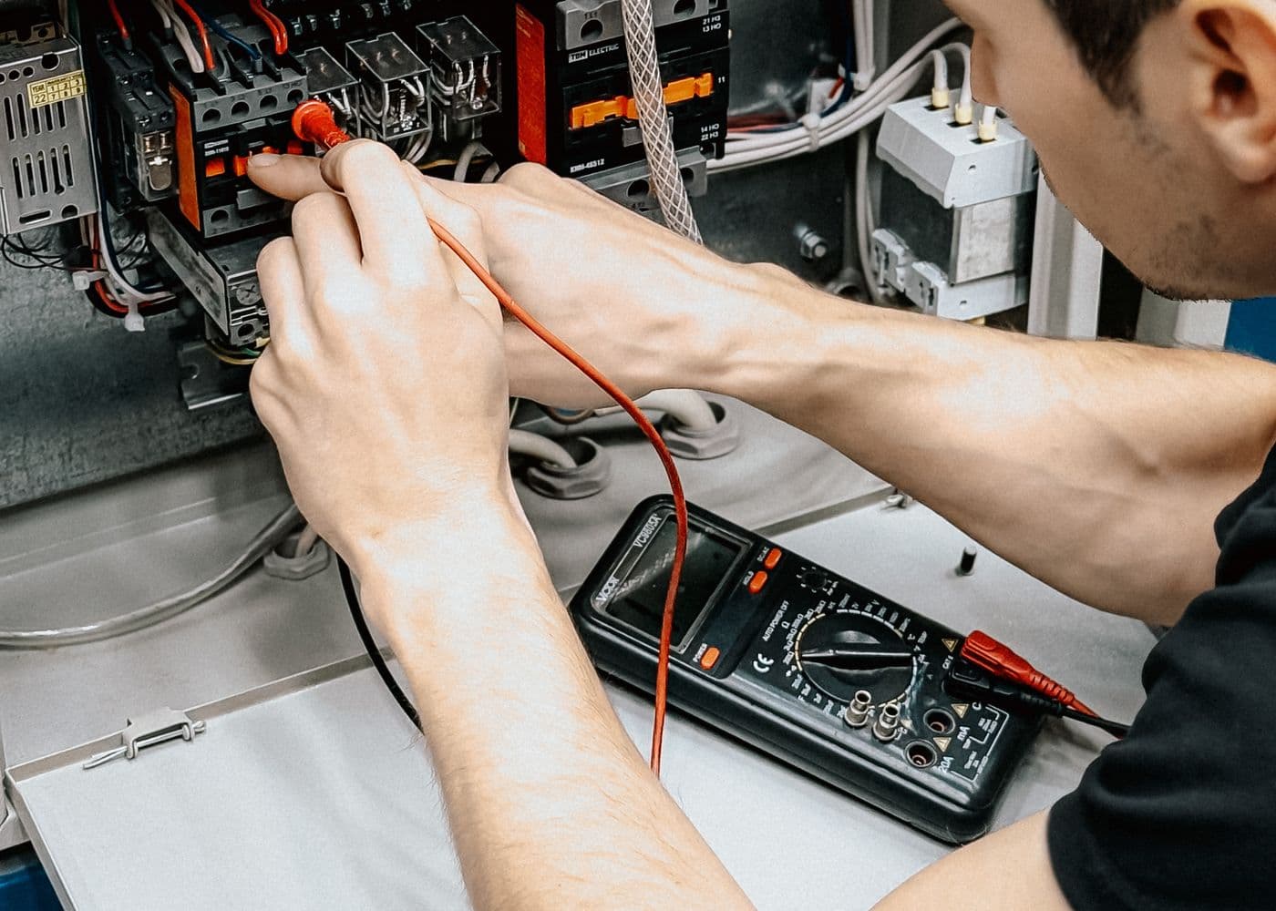
“Ground” can mean several different conductors in a van. Confusing them is the source of many bad diagrams and unsafe shortcuts.
Keep the three functions separate
Plan every current path
Use the free Roam Wired electrical design tool to size the DC system, then have shore-power, inverter and bonding arrangements checked against the equipment instructions and rules that apply to your build.
1. DC negative return
Every 12V load needs a complete circuit back to the source. The most transparent conversion layout uses a negative bus bar:
Battery positive → fuse/distribution → load → negative bus → shunt (if fitted) → battery negative
Dedicated negative wires have several advantages:
- the conductor size and route are visible and documented;
- corrosion at the steel body is not part of the normal load path;
- voltage-drop troubleshooting is easier;
- sensitive electronics are less likely to share unpredictable body paths;
- future owners can understand the installation.
The negative conductor is not automatically smaller than positive. The same current flows in both, so size the complete circuit for current, voltage drop, insulation, routing and temperature.
2. Chassis as a return conductor
Factory vehicle wiring commonly uses the metal body as part of the 12V return. A conversion may also use manufacturer-approved grounding points, but the body is not a magic zero-resistance wire.
Problems arise when builders attach ring terminals to paint, thin sheet metal or random fasteners. Moisture, dissimilar metals, movement and corrosion can raise resistance over time. A poor return can cause voltage drop, erratic electronics, heat and hard-to-diagnose intermittent faults.
If an equipment manufacturer permits a chassis return:
- use an approved structural grounding location rather than drilling blindly;
- protect vehicle systems, fuel lines, brake lines and structural sections;
- remove only the coating necessary for the intended contact;
- use correctly sized terminals, hardware and corrosion protection;
- secure the cable against movement;
- test voltage drop under actual load;
- inspect the point periodically.
For inverters, alternator chargers and other high-current equipment, follow the manufacturer's exact positive and negative connection instructions. Do not assume the body is an adequate substitute for a specified cable.
3. The house-battery chassis bond
Many systems have one intentional connection between house DC negative and the vehicle chassis. Its purposes and required size depend on the vehicle, charging arrangement, fault-protection design and connected equipment.
Avoid creating multiple accidental bonds through device cases, shield drains, negative wires and mounting hardware. Parallel paths make fault current and battery-monitor readings harder to predict. Draw the connections before installation and verify them during commissioning.
4. How a battery-monitor shunt changes the layout
A shunt measures current by forcing the house battery's charge and discharge current through a calibrated resistance. The correct principle is simple:
- Battery side: only the house battery negative connection.
- System side: negative bus, chargers, loads and any intentional chassis-to-house-negative bond.
If the chassis bond is placed directly on the battery side, current returning through the chassis can bypass the shunt. The monitor may then show incorrect state of charge.
Shunt rule
5. 120V equipment grounding is different
In a North American van, the green or bare equipment-grounding conductor connects exposed conductive parts so a fault can operate the protective device. It should not be used as the normal current return. The normal 120V return is the neutral conductor.
Neutral-to-ground bonding in a mobile system depends on the active source and equipment design. Shore power, an inverter and a generator can each change which source is supplying the system. Some listed inverters switch the bond internally; others require a particular external arrangement. Installing an extra permanent neutral-ground bond “just in case” can create objectionable current on the chassis or shore grounding conductor.
Follow the inverter/charger transfer instructions, shore inlet and panel requirements, applicable code and RV standards. Have a qualified professional inspect and test the finished 120V system.
6. Common grounding mistakes
Using a wood screw as a grounding stud
A screw into thin sheet metal is not a documented high-current connection. Use hardware and locations designed for the electrical and mechanical duty.
Painting over an untested connection
Corrosion protection is important, but first verify the joint is mechanically secure and electrically sound. Preserve service access so it can be inspected.
Mounting a terminal over factory seams or coatings
Seam sealer, primer and paint can prevent a reliable connection even when the bolt feels tight.
Letting one device bypass the shunt
Solar controllers, inverters and DC-DC chargers must all return on the system side if their current is to be measured.
Treating 120V ground as a spare negative wire
Never use the protective grounding conductor to carry normal DC or AC load current.
Ignoring isolated and non-isolated equipment
An isolated DC-DC converter separates input and output circuits; a non-isolated one shares a negative reference. This changes the connection diagram. Use the diagram for the exact model number rather than a generic online drawing.
Commissioning checks
Before energizing the system, create an as-built diagram and perform appropriate tests with correctly rated equipment:
- continuity of intended protective paths;
- absence of unintended positive-to-chassis faults;
- polarity at every DC load and outlet;
- voltage drop on positive and negative paths under load;
- shunt accuracy while charging and discharging;
- correct operation of overcurrent and ground-fault protection;
- source transfer and bonding behavior for shore power and inverter modes.
Do not improvise live 120V tests if you are not trained and equipped to perform them safely.
Related guides
Frequently Asked Questions
Keep the build moving
Make the next build decision easier.
Get practical diagrams, calculator updates and honest product comparisons in your inbox.
Roam Wired
Roam Wired turns campervan research into practical plans. We publish transparent guidance, a free electrical design tool and marketplace resources for UK and US van builders.
About our approach